Hi makers! Welcome you to RenderWrench. How are you doing. Hope you are doing great. Let me know in the comment section. With a small recap lets start with 3rd post of RenderWrench Gear series.
Previously we learned about –
In this post we will dive deeper into the world of gearing. Gears are essential component of mechanical Engineering. And in mechanical engineering understanding power transmission is a non- skippable. Gears plays very major role in power transmission. And in this post we will learn “how Gears transmit motion and power?” and related topics.
How Gears transmit Motion – Friction wheels to gears evolution
In order to understand how gears transmit motion one shaft to an other, let’s discuss some theory first. Consider two circular wheel pressed against each others shown in the image bellow.
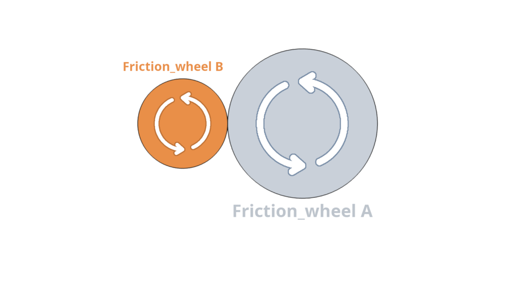
Now consider this two wheels are Tom and jerry. When Jerry rotates the Tom rotates in the opposite direction. Tom Rotates as long as the tangential force between Tom and Jerry exceed the maximum frictional resistance between them. The moment this happens both start slipping.
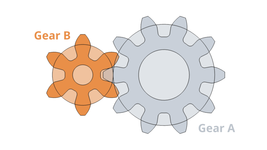
To avoid Slipping tooth are introduced on the periphery of the both wheels. Now our Tom and Jerry are become Gear A and Gear B. If you think carefully kinematically Pair of two friction wheel like Tom and Jerry, Gear A and Gear B are identical. Gear teeth are just an evolution to fight against spiling.
So after successfully overcome slipping, our pair of gears can transmit Motion to shaft 1 to the shaft 2 seamlessly. So, now we know “how gears transmit motion”.lets move on to the next part.
Direction of motion – Same or Opposite?
While studying gears or design a gear train, sometimes it may confuse you the direction of gear rotation. In a gear train all gears never rotate in same direction. For example- a pair of spur gears always rotate in opposite directions. Now it may seems simple, but in large gears trains some time it can get really confusing. Let’s understand this more clearly-
External Gears
In the previous example, we saw external gears where teeth are cut on the outside. in this case, meshing gears always rotate in opposite direction.
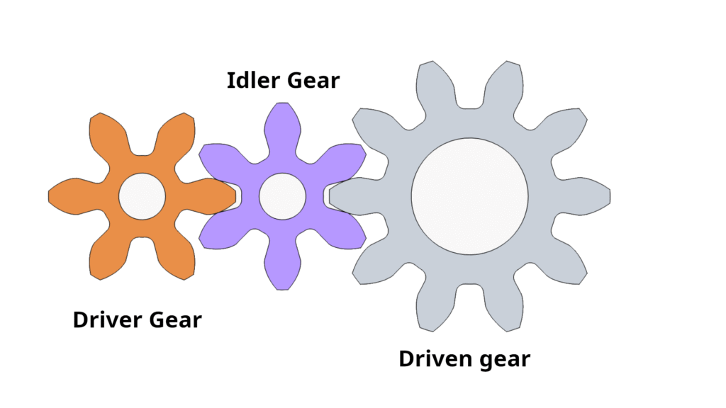
Idler Gear
Now say, you’re driving a gear with a motor that turns a pinion, now on the output shaft you want the rotation is in the same direction of motor rotation.
In that case you put an extra gear in between the pinion (the driver) and the gear (driven). Now you see the rotation of the motor and output shaft rotation in same direction. The extra gear we put in between other two gears is called an Idler gear.
We will see many other use-case of the idler gear latter on the series.
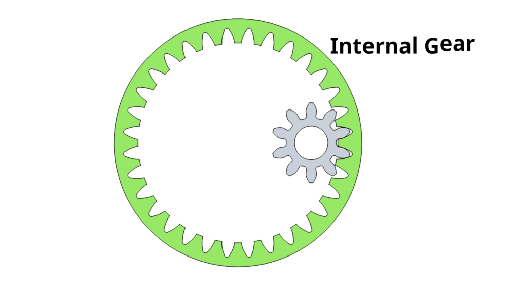
Internal Gears
Internal gears are quite different. Instead of teeth cut on the outside of the gear- teeth are inside the gear body. It’s basically a gear with teeth on the inside, resembling a ring Sometimes called ring gear. Mostly seen in planetary gear box. This type of gear rotates in the same direction of the driving motors.
There are many other types of gears like bevel gears, crossed helical gear, worm gears that transmit the motion differently to the output shaft. We will discuss them in the series in depth. Now let’s move on to the next speed and torque relation of gears.
Speed and Torque Relationship – The Heart of Gear Power
have you ever looked inside remote-controlled toy cars? I used to open then every time I got one. If you’ve ever seen in side, there is small pinion attached on a DC 5v motor that powering the toy car. The pinion rotate a larger gear attached to the rear wheel shaft. Now if you observe closely, you will see the motor spins much faster than the wheels themselves. But if you try to stop the motor while it’s running, it’s quite easy to hold but on the wheel shaft, the torque is increased. Wheel shaft is not easy to grab. That means whenever torque increases, speed decreases — and vice versa.
Gear ratio fundamentals
Gear ratio is very important parameter for gear design. Without it, you can’t design a working gear train. Let’s understand this with the same toy car example. Here, the small pinion is the driver, and the large gear on the shaft is the driven gear.. The pinion has 10 teeth.. The pinion has 10 teeth.. Now,
Number of teeth on pinion = 10 = Z1
Number of teeth on gear = 40 = Z2
Therefore, Gear Ratio = i= Z2:Z1 = 40:10 = 4:1
This means the motor spins 4 times faster than the wheel and the wheel rotates with 4 times more torque than the motor. That’s how the gear ratio determines both speed reduction and torque multiplication.
Power balance and efficiency
Gears are all about power transmission. So, let’s discuss how efficiently gears do transmit power and how to calculate it. Ideally, the power we put on a gear train, the same amount of power we get on out output shaft. But this is not the case. As we know as engineers there is no mechanism with 100% efficiency.
Power transmission between gears
So a gear train don’t produce any power by it-self. The power we put on the input shaft of a gear train multiplies its as per its gear ratio.
There is very common power equation- P = T x ω
where, P = Power
T = Torque
ω = Angular Speed
now let us assume, it’s an ideal world with no losses. So we get the same amount of power form output- shaft as we give to the input shaft. In that case, power transmitted to the one gear to another will be like,
P = T1 x ω1 = T2 x ω2 = ……… = Tn x ωn (for n number of gears in the gear-train)
Here you can see, power transmitted by each gear is same but the torque and speed keep changing. This change depends on Gear ratio (i). now lets discuss efficiency.
Efficiency — The Real-World Factor
Coming back to real-world, gears are not 100 % efficient but they are quite efficient,
let’s discuss now how to calculate efficiency?
Efficiency(η) = output power/ input power
You put some power in driver shaft of a gear train, there are some losses in between, you get a power in output shaft, divide them. You will get the efficiency.
Why gear efficiency drops?
The losses you faces due to, 1. the Friction between the teeth of meshing gears, 2. if gears faces any misalignment that cause the efficiency drop. 3. You forgot to lubricate the gear box. Just like when you forgot to change engine oil. The same thing. There could be many more reasons behind the efficiency drop but these are the most common. If some think else come in your mind let me know in the comment.
Example
Let’s understand the theory we discussed so far with an example.
Let’s say a motor delivers 0.32 N.m of Torque to the input shaft of a gear train. The gear ratio is 5:1, and the efficiency is 95%. and the motor is spinning at 3000 RPM.
So, from here we can calculate the output speed = input speed / gear ratio = 3000/5 = 600 RPM.
And Output torque = Input torque × Gear ratio × (Efficiency/100) = 0.32 × 5 × 0.95 = 1.52 N·m
Now you can clearly see how a gear system works. The RPM (revolutions per minute) is reduced by 5 times, while the torque increases by roughly the same factor. But there is a loss in torque transmission due to the efficiency factor of the gear train.
So with that, let’s wrap up this post I hope you enjoyed this post and found it helpful. The next post in this series will be “Gear Materials & Manufacturing Methods”. So stay tuned with Render wrench. Bookmark this page and follow RenderWrench on social media to get notified whenever a new post arrives.
“Every gear train follows this simple truth — you trade speed for strength. Understanding this balance is what turns a good design into a great one.” Happy making!
Follow RenderWrench on Instagram


Pingback: Gear Basics to Advanced : a complete guide (RenderWrench Gear Series) - RenderWrench