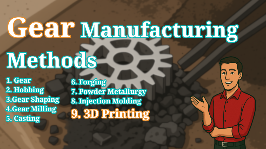
Hi makers! Welcome back to a brand-new post of the RenderWrench Gear Series. Hope you’re doing great today! In the previous post, we explored gear materials and understood why a toy-car gear can’t survive inside a real car. In this post, we take the next big step:
How are gears actually made?
As a maker, engineer, or hobbyist, you’ve probably noticed that some gears run buttery smooth for years, while others crack, wear out, or become noisy quickly.
Most of this depends not only on the material, but also on the manufacturing method used.
Different applications need different methods—
A gear in a wristwatch is made entirely differently from a gear in a crane or an automobile.
So today, let’s dive deep into how gears are manufactured, their processes, pros, cons, and where each method is used.
Why Gear Manufacturing Method Matters
Choosing the right manufacturing method affects everything about a gear:
- Strength → Does the gear survive high torque?
- Accuracy → Does it run smoothly or make noise?
- Durability → Does it last years or wear out quickly?
- Cost → Is it cheap for mass production or expensive for precision?
- Volume → Some methods are ideal for a single prototype, others for millions of units.
Just like choosing the right material, selecting the correct manufacturing method ensures the gear works exactly as expected.
Major Gear Manufacturing Methods
Let’s break down the most common manufacturing processes you’ll see in industry—and in DIY projects.
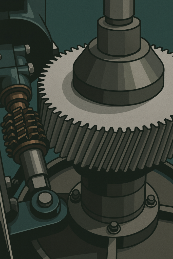
Gear Hobbing — The Industry Standard
Gear hobbing is the most widely used method for making spur and helical gears. at first glance it may seems magical, but it’s a rotating cutting tool called a hob slowly cuts teeth into a rotating gear blank. its a very efficient process to manufacture gears. I used to design Gears for SPMs to be manufacture gears in this process.
Why hobbing is popular
- High accuracy
- Great surface finish
- Fast production
- Suitable for medium to large volumes
Best for
Automotive gears, industrial gearboxes, machine tools.
Gear Shaping — Best for Internal Gears
This is a very straight forward process.Gear shaping uses a cutter that moves up and down like a shaper tool, cutting teeth as the gear blank rotates. I personally never used this process to manufacture gears.
How It Actually Works (Detailed Explanation)
Gear shaping is one of the most versatile gear manufacturing processes used to cut internal and external gears, spur gears, helical gears, and even shoulder gears where other methods fail.
The magic of gear shaping is simple: a cutter shaped like a gear cuts another gear while both rotate together.
1. Basic Principle — “Gear cutting by a gear”
The tool used in gear shaping is called a shaper cutter. It looks like a small pinion gear but with cutting edges ground on its teeth.
- The cutter reciprocates (moves up and down).
- The workpiece rotates slowly.
- During the downstroke, the cutter removes material.
- During the upstroke, it clears and indexes for the next cut.
This synchronized motion ensures the cutter generates the exact gear profile on the workpiece.
2. Why Gear Shaping Is Used
Gear shaping works where hobbing or milling can’t.
It can cut:
- Internal gears
- External gears
- Shoulder gears
- Cluster gears
- Helical gears
- Spline shafts
- High-precision profiles (module 0.5 to module 10+)
Can work with:
- Steel
- Aluminum
- Cast iron
- Plastics (for prototyping)
Key advantages
- Excellent accuracy (up to DIN 6–7 quality)
- No need for special clearance around the part
- Ideal for internal gears
Gear shaping uses 3 main motions:
3. Machine Movements in Gear Shaping
1. Reciprocating Motion (Primary cut)
The cutter moves up and down 200–1500 strokes/min.
2. Rotational Motion
The cutter and the workpiece rotate in a fixed ratio
(same as the gear tooth ratio).
3. Feed Motion
Slow radial in-feeding to deepen the tooth gap with each passes until full depth is reached.
4. Types of Gear Shaping Cutters
A) Disc-type shaper cutter
Used for external gears.
B) Pinion-type cutter
Looks like a small spur gear.
Used for both internal and external gears.
C) Helical shaper cutters
For cutting helical gears.
The cutter must match the helix angle.
5. The Full Gear Shaping Cycle
- Setup the workpiece on the arbor or fixture.
- Mount and align the gear shaper cutter.
- Machine starts:
- Cutter reciprocates
- Workpiece rotates
- Cutter feeds radially
- Roughing passes remove bulk material.
- Finishing passes improve accuracy.
- Deburring and heat treatment (optional).
- Final inspection using:
- Gear measuring machines
- Profile testers
- CMM
6. Where Gear Shaping Is Used (Industry Applications)
- Automotive transmissions (internal ring gears)
- Planetary gear sets
- Industrial gearboxes
- Robotics gear trains
- Aerospace mechanisms
- Agricultural machinery
It’s especially important for internal gears in planetary drives, where no other method works as efficiently.
7. Gear Shaping vs Hobbing (Quick Comparison)
| Feature | Gear Shaping | Gear Hobbing |
|---|---|---|
| Internal gears | ✔️ Best | ❌ Not possible |
| External gears | ✔️ | ✔️ Faster |
| Precision | High | Very high |
| Speed | Slower | Faster |
| Helical gears | Yes | Yes |
| Shoulder / restricted gears | ✔️ | ❌ Needs clearance |
| Tool shape | Pinion-like | Worm-like hob |
8. When Should You Choose Gear Shaping?
Choose shaping when:
- The gear is internal
- The part has shoulders / obstructions
- You need medium-to-high accuracy
- Batch size is medium (not huge)
- Gear geometry is complex
If you’re making a planetary gearbox, the internal ring gear cannot be cut by a hob because the hob must swing around the gear. Zero clearance means zero machining.But a shaping cutter fits inside easily, rotates like a gear, and generates the internal teeth perfectly.That’s why shaping dominates internal gear production.
Why shaping is special
- Can make internal gears
- Works for gears with shoulders, hubs, or obstruction
- Good accuracy
Best for
Planetary gearbox ring gears, internal spur gears.
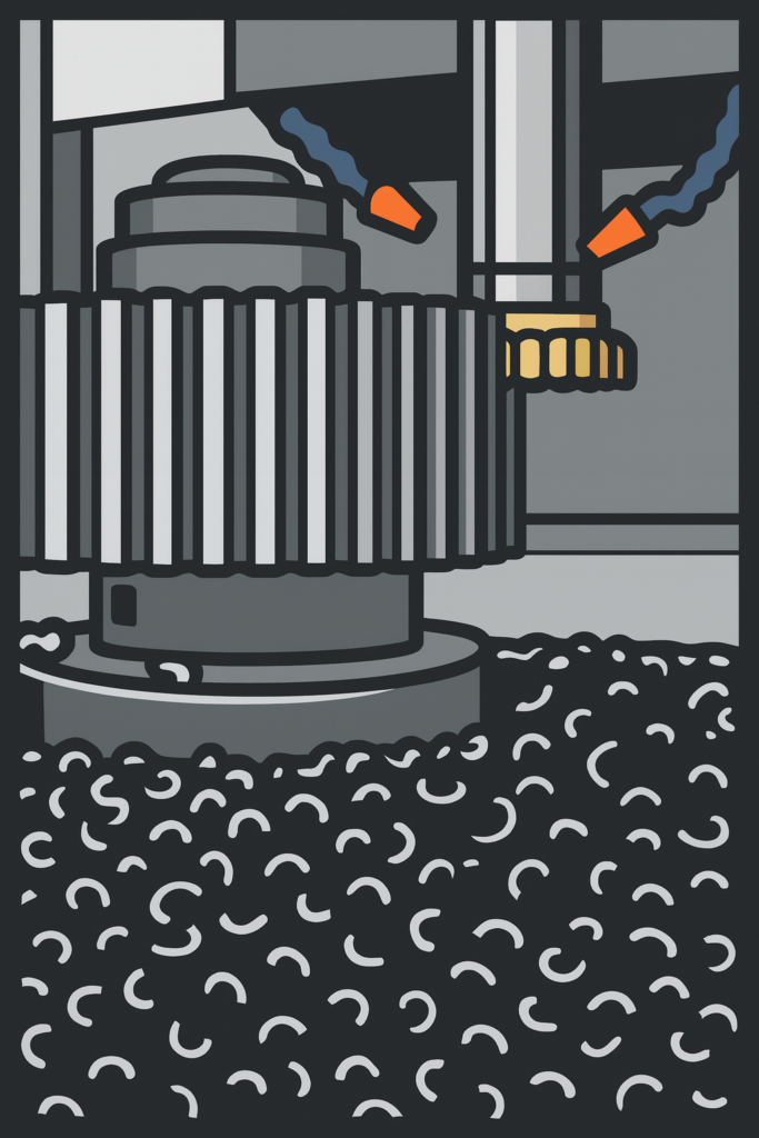
Gear Milling — Flexible & Maker-Friendly
Gear milling uses a CNC machine with a form cutter or end mill to carve the gear teeth. while collage days My and my collage team, made gear on CNC, and i am the one who write the G-code for the CNC machine. while writing, I still can fill that enthusiasm working on CNC machines.
Advantages
1. Extremely flexible for custom designs
Gear milling doesn’t lock you into standard gear sizes or profiles. You can easily tweak tooth count, face width, or even experiment with non-standard designs. This makes it perfect when you’re building something custom—like a robot, a prototype gearbox, or a one-off mechanism.
2. Ideal for prototyping and learning
For makers and students, gear milling is one of the best ways to learn how gears are actually made. You can see the toolpath, understand tooth geometry, and directly connect CAD design with real-world machining. From personal experience, writing G-code for gear milling teaches you far more than just pressing “start” on a machine.
3. No specialized tooling required
Unlike hobbing, gear milling doesn’t demand expensive, dedicated hob cutters. A standard end mill or form cutter can get the job done. This lowers the entry barrier significantly for small workshops, college labs, and DIY CNC setups.
4. Works well for low-volume production
If you only need one gear—or maybe a handful—milling makes total sense. There’s no setup overhead like custom tooling or long machine preparation. Design it, generate G-code, and start cutting.
5. Compatible with common CNC machines
Most 3-axis CNC mills can perform gear milling. You don’t need a dedicated gear-cutting machine, which makes this method very maker-friendly.
Limitations
1. Lower accuracy compared to hobbing
While gear milling works, it’s not the most precise method. Tooth profile accuracy and surface finish are generally inferior to hobbing or grinding. For high-speed or high-load gearboxes, this can become a problem.
2. Slower for larger quantities
Gear milling is a tooth-by-tooth process. That means machining time increases quickly as tooth count and batch size grow. If you’re making dozens or hundreds of gears, milling becomes inefficient.
3. Requires careful programming
Good results depend heavily on correct G-code, toolpath strategy, and cutter selection. A small mistake in indexing or depth can ruin the entire gear. This is great for learning—but risky if you’re under time pressure.
4. Surface finish may need post-processing
Milled gears often require deburring or light finishing, especially if they’re meant to mesh smoothly. Without this, noise and wear can increase during operation.
5. Not suitable for high-precision industrial gearboxes
For applications like automotive transmissions or high-speed industrial machines, milled gears usually don’t meet performance and durability requirements.
Best for
Custom gears, robotics projects, DIY repairs.
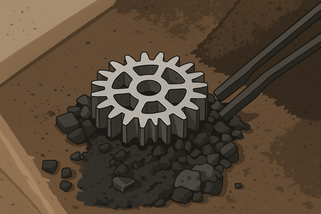
Casting — For Large & Low-Speed Gears
this process old but gold. still large gears are make with this process. Casting involves pouring molten metal into a mold shaped like the gear.
Why casting is used
- Very cheap for large gears
- Good for low-speed applications
- Material options: cast iron, bronze, aluminum
Limitations
- Poor accuracy
- Not suitable for high-speed or high-load applications
Best for
Heavy machinery, pumps, agricultural equipment.
Forging — The Strongest Gears in the Industry
In forging, heated metal is pressed into shape with massive force. This aligns the grain flow and makes extremely strong gears. while freelancing, I used to visit large factories. like this I encountered a large machine and i was completely overwhelmed. ahhhh…. good old days.
Benefits
- Exceptional strength
- Perfect for high-shock applications
- Durable for decades
Limitations
- Expensive
- Requires post-machining
Best for
Automotive transmissions, aircraft gears, heavy-duty equipment.
Powder Metallurgy — Cheap & Mass-Produced
Metal powder is pressed in a die and sintered to form a gear.
Benefits
- Extremely low cost
- Good for medium strength
- Perfect for high-volume production
Limitations
- Lower strength than forged or hobbed gears
- Porosity causes reduced fatigue life
Best for
Car window motors, printers, household appliances.
Injection Molding — How Plastic Gears Are Born
this process is the dominator of modern plastic Gear manufacturing. Next time you see a plastic gear, 90% chance that made with Injection molding. Molten plastic is injected into a mold shaped like the gear.
Benefits
- Super cheap for mass production
- Perfect for quiet operation
- Complex shapes possible
Limitations
- Only for plastics
- Not for heavy loads
Best for
Toys, electronics, small appliances, printers.
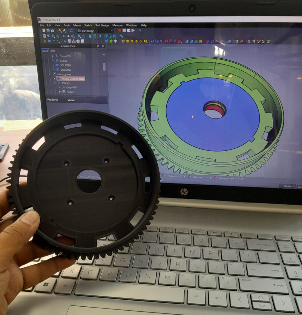
3D Printing — The Maker’s Manufacturing Method
My personal favorite. I don’t remember, how much time I spend sitting in-front of a 3d printer watching it’s printing a gear. For prototyping or low-load applications, 3D printing is an amazing option. ever today a gear is printing in my office.
Types used
- FDM → PLA, ABS, PETG
- SLS → Nylon powder
- Resin printing → For fine details
Benefits
- Fast prototyping
- Cheap for small quantities
- Easy to customize
Limitations
- Not strong enough for high-load applications (unless using SLS Nylon or composites)
- Layer adhesion affects reliability
Best for
Robotics, DIY projects, prototypes.
Gear Quality Grades — Why Precision Matters
Even two gears made of the same material can perform differently because of tolerances and quality grades.
High-quality gears:
- Run quieter
- Have higher efficiency
- Produce less vibration
- Last longer
Low-quality gears:
- Produce noise
- Wear quickly
- Cause backlash
Industry uses AGMA or ISO quality grades to classify gear precision.
How to Choose the Right Manufacturing Method (Simple Guide)
| Requirement | Best Method |
|---|---|
| High precision | Hobbing, Shaping |
| High strength | Forging |
| Mass production (cheap) | Injection molding, Powder metallurgy |
| Custom / prototype | CNC milling, 3D printing |
| Internal gears | Shaping |
| Large diameter gears | Casting |
RenderWrench Quick Advice:
- Building a robot? → 3D printing or CNC milling
- Making a gearbox? → Hobbing or shaping
- Need huge industrial gears? → Casting
- Need extreme strength? → Forging
Maker Example — Real Experience
In many of my projects, I prototype gears using 3D printing, test them, then switch to machined or off-the-shelf metal gears for the final design.
This saves:
- Time
- Money
- Material
- Iteration effort
And it’s one of the best workflows for makers.
So makers, now you know exactly how gears are made and why the manufacturing method is just as important as the material. From hobbing to forging, from injection molding to 3D printing—each technique has its own strengths and ideal applications.
In the next post of the RenderWrench Gear Series, we will learn:
👉 Backlash, Interference & Contact Ratio Explained — Why Gear Teeth Don’t Always Mesh Perfectly
So bookmark this page, follow RenderWrench on social media, and stay tuned for more!
Happy making! ⚙️🔥
Follow RenderWrench on Instagram


Pingback: Gear Materials Explained : Strength, Durability & Choosing the Right Material (RenderWrench Gear Series #4) - RenderWrench
Pingback: Complete Gear Guide: Basics to Advanced Concepts Explained Simply (RenderWrench Gear Series) - RenderWrench