Hey maker! How are you? I am just fine. Hope you’re good too.
So, have you ever got lost in technical terms like addendum, dedendum, Module, PCD, gear ratio etc.
You are not alone. Me too, I remember, me struggling with books and internet understanding terminology while gears in my early days as Student.
I faced a main problem that it’s really hard to find all related teams in one place with good explanation. So I’m here with all important terms related to gears to begun with.
Here is a use full link you can follow, here I explained how you can design meshing gear in FreeCAD – Click here
Why gear terminology is important-
Think you’re designing a gear or more possibly a gear train, what do you want out of that?
- It runs smoothly.
- No cracking sound comes out of it.
- Delivers your desired Torque and speed
- and many more.
To achieve all these out of any geared mechanism we need to know Gear Terminology.
This knowledge will help you to –
- Design gears that mesh correctly.
- Avoid interference or mismatched teeth.
- Understand real-World gear performance.
What Is Gear terminology?
Designing gear need to follow some parameters to define those there needs to have some standardised parameters like tooth shape, spacing, motion.
This despite of gear type either it’s a spur gear, helical gear, bevel gears or any other type of gears this fundamentals are remain same across them but there are some gears that needs more. We will discuss them later.
We will discuss some important gear parameters in this part of series. Those are,
- Pitch Circle Diameter
- Module
- Circular Pitch
- Addendum
- Root diameter/ Dedendum
- Gear Ratio
- Center Distance
- Pressure angle
Let’s discuss these in details.
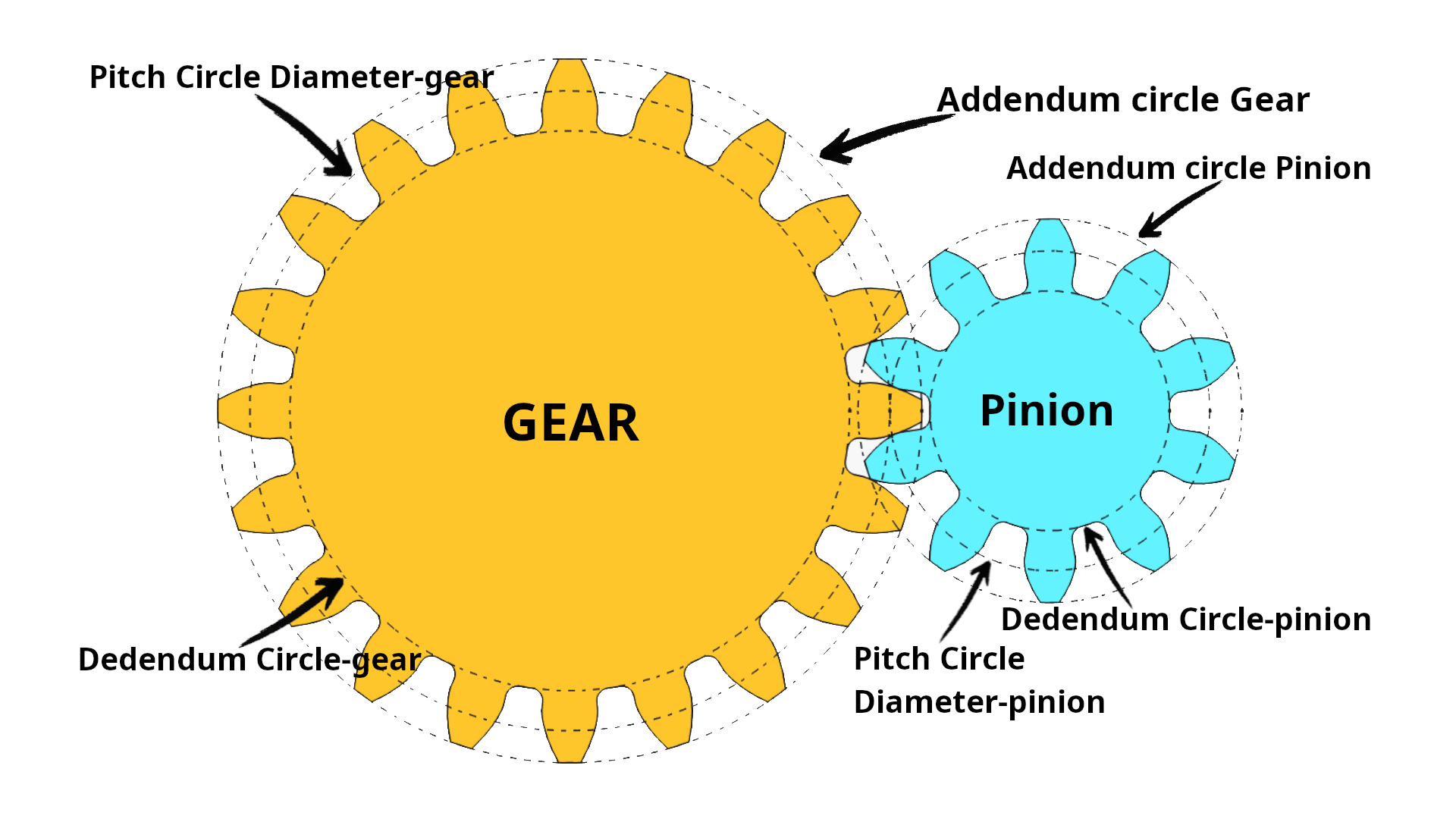
Pitch Circle diameter- The imaginary circle that rules all (D)
Pitch circle Diameter is an imaginary circle where meshing gears mesh smoothly.Pitch circle diameter is widely represented by later ‘D’ or ‘ PCD’. We will call it ‘D’ for this series.If you know module and number of teeth of the gear you can calculate D easily
D= m x Z [where, Z= number of teeth]
D is very important to calculate Center distance between two meshing gear. We will discuss Center distance later on.
For me Pitch circle diameter is the gangster of gear terminology, “you can you can’t see this but it means a lot.”
Module- The Scale of Gear (m)
Module is the ratio between Pitch circle diameter(D) and Number of teeth(Z).module is widely represented by later ‘m’
m=D/Z
Overall size of a Gear depends on Module. The fun facts it two gear only mesh if they there module is same.
Circular Pitch- The tooth Spacing (p)
Image
Circular pitch is the distance between two corresponding points of two consecutive teeth. Circular pitch is widely represented by later ‘p’
p= π x m
How closely the teeth are spaced and how smoothly two gears will mesh and torque transfer closely depends on Circular pitch.
But while design gears most of the time you don’t needs to worry about this. Design software mostly take care of it.
Addendum- Tooth Height Above Pitch Circle
Addendum is the radial distance form pitch circle to the tooth tip of gear. It’s determines how two meshing gears engages with each other. While design a gear this part of the the gear terminology is taken cared by design software.
Dedendum- Tooth Depth Below Pitch Circle
Dedendum is the radial distance from Pitch circle to the root of teeth. Dedendum provides clearance to the teeth of meshing gears. More the dedendum more the clearance. But empirically it’s 1.25 times of module (m).
While design a gear this part of the gear terminology is taken cared by design software.
Pressure Angle- The line of Force
The angle between the line of action is called pressure angle. It’s always tangent to the pitch circle.
The most common value is 20 degree. it’s maximised the teeth strength. But if you want a smoother operatio then the pressure angle should be 14.5 degree. But 14.5 degree pressure angle makes the gear teeth weaker.
Gear ratio- The Relationship of Speed & Torque (i)
Gear ratio is the ratio of number of teeth of two meshing gears, widely represented by latter ‘i’.
i=Z2 : Z1 [Where, Z= Number of teeth]
now lets understand Gear ratio with an example. Say a 10 teeth pinion driving a 40 teeth gear. So here, i = 40 : 10 = 4:1
that means the torque input to the pinion is increases 4 times to the gear, but speed decreases by 4 times. As, if i >1, output RPM slower but more Torque as we show in the example and if i<1, output RPM is increases but less Torque is transmitted.
With this much, you know all basic and important terminology of gears.
If not..read it again or ask me in the comment.
Center distance
Center distance is very important parameter for mashing gears. if center distance of two mashing gears is not correct, that’s can cause very tight gear or a slipping gear. If center distance is too less it will cause a tight gear. If the center distance is more then required it will increase the backlash.
To calculate center distance we need to know “PCD” of both pairing gears.
let’s say, I have a Gear and a pinion PCD of Gear is D1 and the PCD of pinion is D2.
Therefore, Center distance = {(D1/2)+(D2/2)}.
Here are some important points to note
- PCD = m x z
- Pitch = π x m
- Addendum + Dedendum define tooth shape
- Pressure angle defines contact
- Gear ratio defines Speed and torque transmission.
Bookmark this page on your browser or follow RenderWrench on social media for updates on every new gear series artical. Thank you. Happy making.
Here is the link of main Content page where you can find all Gear series summary. Link


Pingback: How Gears Transmit Motion & Power (RenderWrench Gear Series #3): Direction, Gear Ratio & Torque Basics - RenderWrench
Pingback: Gear Basics to Advanced : a complete guide (RenderWrench Gear Series) - RenderWrench
Pingback: What Is Backlash in Gears? And why every maker should know this - RenderWrench
Pingback: Spur Gear Design in FreeCAD – Step-by-Step CAD Tutorial (RenderWrench Gear Series #6) - RenderWrench